Background
This project is to build a full size reproduction of the one-man space pod used in 2001, and came about since I haven't been able to find one of the original pods. So why do it? Well the pod represents the ultimate one man spacecraft, and it would be a good challenge to try to reproduce it. However, I have been putting this project off for many years because:
1) I did not have enough information to make a reproduction accurate enough to be happy with, and
2) I was always hoping I would find one of the original pods (see Raiders of the Lost Props). ( I keep hoping for this to happen, but there is strong evidence they were destroyed along with the other props and sets.)
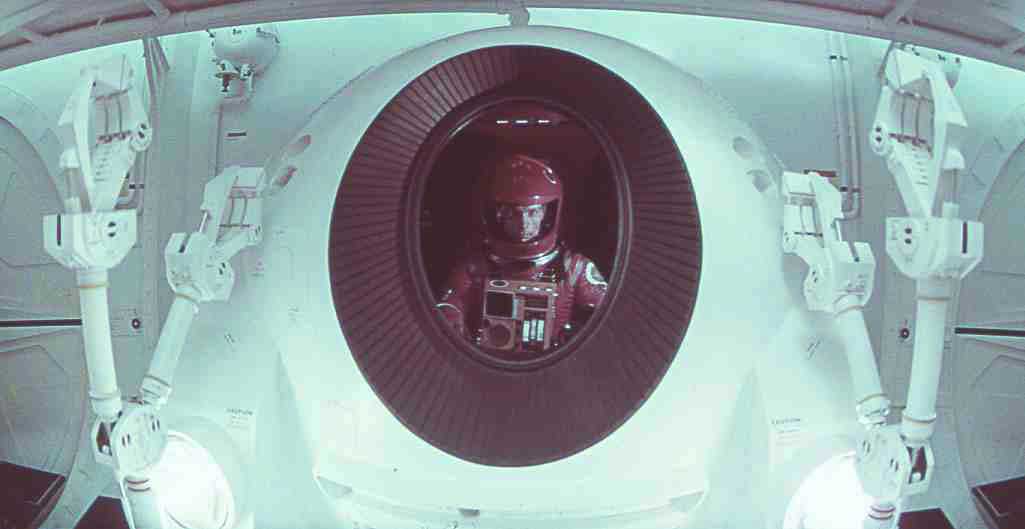
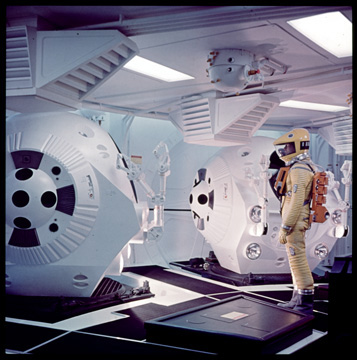
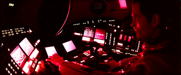
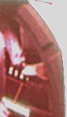
It is well known (Agel "Kubrick's 2001" c.1970) that there were 3 full size Pods built for the pod bay set, two had operational doors and mocked-up interiors. A fourth pod was built for filming the EVA rescue scene, and was full of servo motors and drive mechanisms for controlling the pod arms. A separate interior Pod set was built for filming interior scenes. The image above, of Bowman in one of the pods, shows that at least one of the pods with a mocked-up interior had lighted overhead control panels in the pod.
There are 3 versions of the pod one can make as a reproduction: 1) exterior only version, 2) interior only version (ie like a simulator), or 3) a full-up pod with interior. Of course if one was to do the interior, then it would have to have lighted switches, operating flat screens, etc... My plan is to make a complete pod with functioning interior. Ok, now that is easier said than done, since some parts of the pod design are not well understood. This is especially true with the interior of the pod, as many parts are not clearly visible in the film, and some parts do not even show up in fhe final cut of the film.
I took the approach that, since the exterior is fairly well documented, the hardest part (from a completeness and accuracy standpoint) would be to make the interior. If I could not reproduce the interior to a level of accuracy that I would be happy with, then I was not going to do the project.
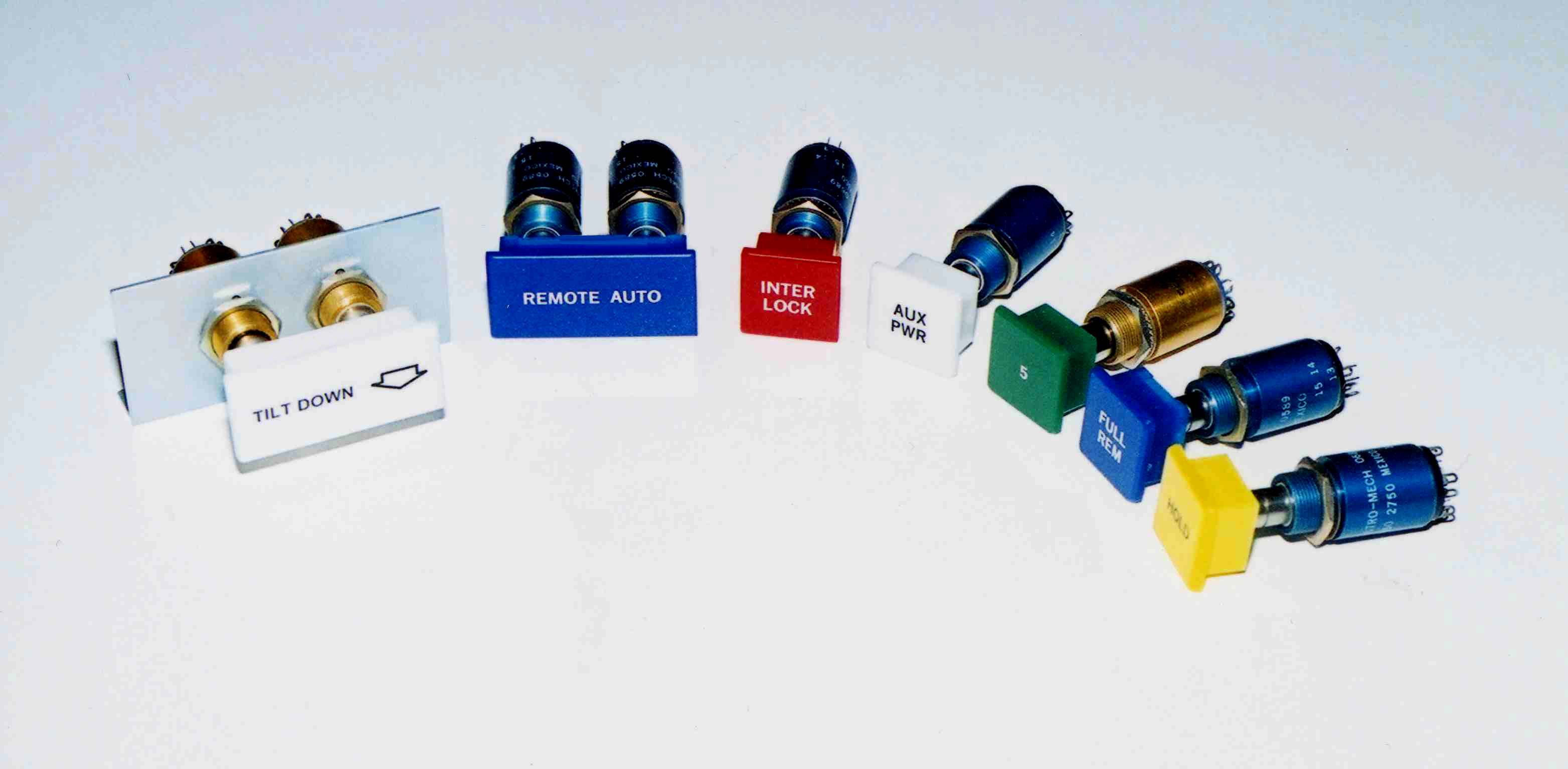
Over the years, I have been collecting pictures and information in order to reproduce one of the Pods. In addition, I have recently determined what was used for a significant component inside the pod. I now believe I have enough information to make a good attempt at reproducing a full size pod. Also, several people have been encouraging me build a pod, so all of these factors have convinced me to go ahead with replicating the pod. However, there are still some areas of the pod interior that are not fully understood (seat area, inside of door, area immediately around the seat, and the foot-well area.) So I am still researching these areas. Most of the interior parts consist of flat control panels with lighted push button switches. These would be fairly easy to replicate. The most difficult items inside the pod to replicate are the hand controllers for the pod attitude and velocity control, the hand controls for the pod arms (some call these the Waldo controllers), and the explosive bolt arming unit.
Pod Design Overview
This section privides a discussion on the design of the pod as seen in the film.
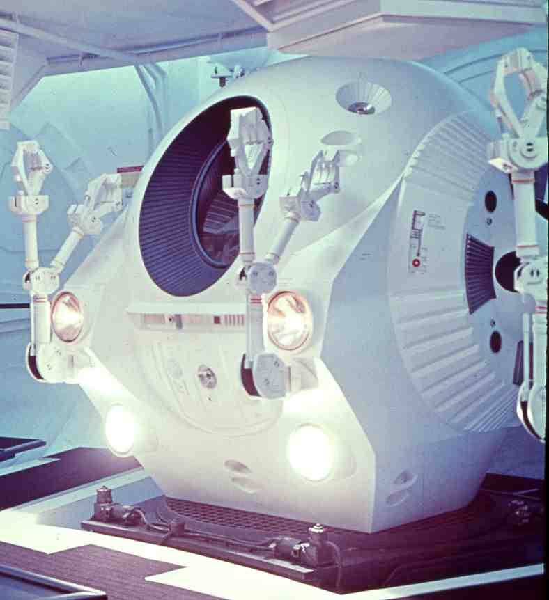
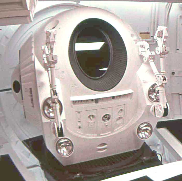
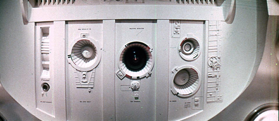
The upper part of the outside shell of the pod is basically spherical in shape and transitions into a multi-faceted bottom structure. Attitude control rocket engine clusters are attached on the left and right sides, with the main axial engine recessed into the underside of the vehicle. An oval window is recessed into the front wall with an egress hatch in the rear. Various details are positioned around the outside of the vehicle, such as cameras and hand holds for EVA (Extra Vehicular Activity). A highly detailed panel is located directly below the viewing window. This panel difers between the pod in the pod bay and the separate EVA pod with the replacement of the front looking camera lens with the HAL lens. Recently, excellent observations by some members of the Pod Working Group Forum (see Links) have pointed out other differences in the front panel between the two pod versions. My approach is to make the EVA version.
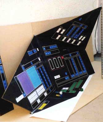
The 2001 pod was designed with the pilot located at or near the center of the spherical shell that makes up the pod. This was done so that he is able to reach all controls surrounding him. This point is key to understanding the layout and orientation of the control panels. The interior wall on the upper half of the pod is a spherical shell, which is a different shell (smaller diameter) than the outside spherical shell. The control console panels are fitted within the inner shell, around the pilot on three sides.
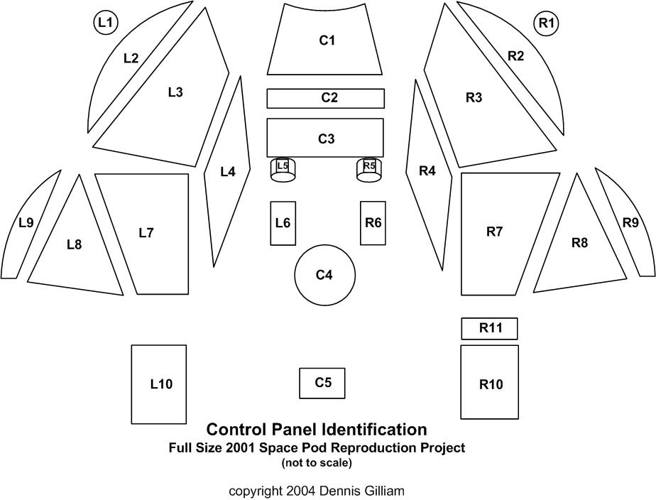
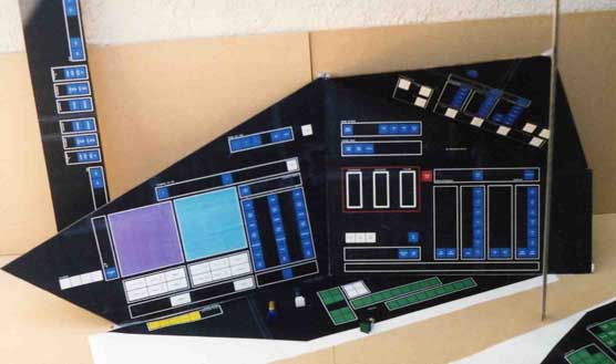
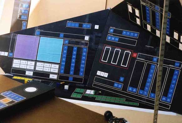
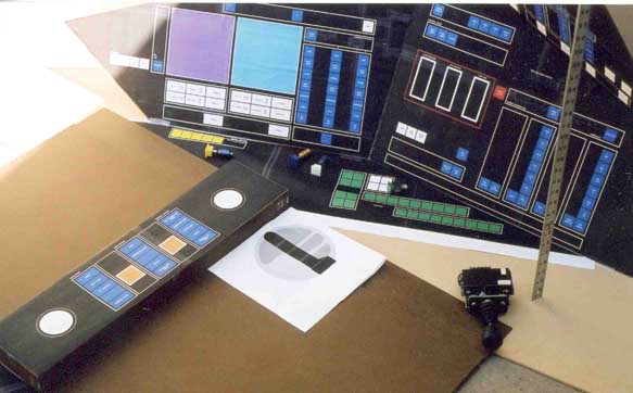
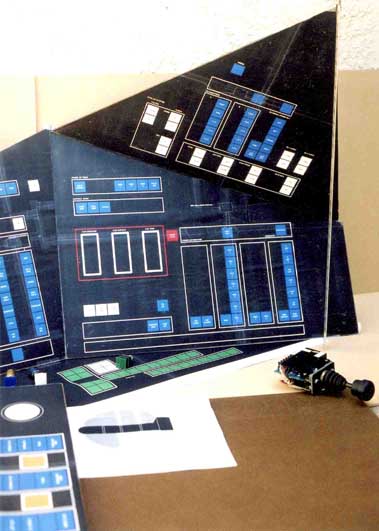
The overall layout of the pod interior is symmetric about the fore-aft centerline vertical plane, so that the left and right sides are primarily mirror images of each other. There are differences in the number and layout of switches on the panels, but the size and location of the panels are similar. The panels are mostly flat sheets with lighted buttons and flat panel display screens mounted in them. Two panels have vertical tape indicator instruments mounted in them, three on the pilot's right and 6 on the pilots left. The vertical tape instruments will be difficult to duplicate, especially if they are to be functional. More on this later. There are a total of 26 panels, most of them have controls or switches on them. At last count there were slightly under 500 lighted push button switches. This may vary by a few as more detatil on some of the internal items are uncovered, especially on the controls mounted to the door's inner surface.

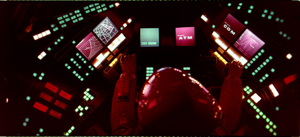
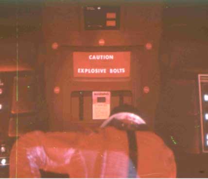
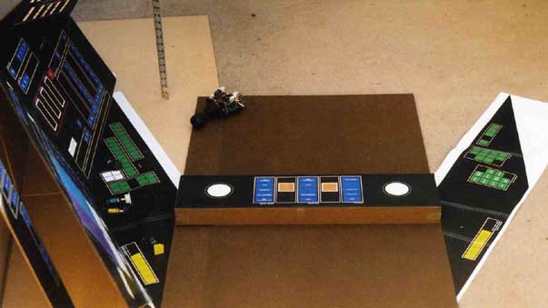
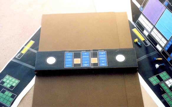
The center console panel of the pod contains two three-axis hand controllers for pod attitude and velocity control, and the two controls for the pod arms (some call these the Waldo controllers). The panel over the pilot's right shoulder contains the device for arming the emergency hatch explosive bolts.
There are 5 interior cabin lights, represented as rectangular lighting panels. When not illuminated the light lens is white and when illuminated (light on) the light emited is red. There is some evidence that the lights may have been capable of emiting both red and white light. (A photo in the Kubrick Exhibit catalog shows additional lights installed with baffles, but they were obviously only installed for filming purposes and not a part of the pod interior.)
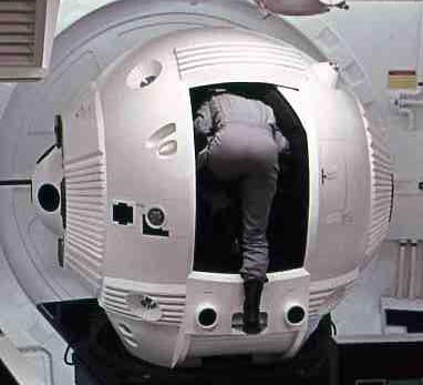
A very short entry way leads from the door opening to the pod cabin. The sides of this entryway is padded in the same style as the command section of the Discovery, with separate padded panels mounted to the wall surface. There are three hand holds on the interior for assisting getting into the pod, one on each side of the padded entryway, and one overhead.
The door of the pod is made of two sections; the door frame/structure, and the removable center hatch. When the door is opened it is motor driven to the right (as viewed from the rear exterior). The door is pivoted at the top center of the pod (circular access cover, which covers up the pivot assy is visible on the top of the pod exterior) and the bottom door edge is driven along a track. Since the door is inside the pod wall, it should move slightly outward at the end of its travel in the closed position to provide a seal with the wall. When the door is in the open position, the top left edge is visible protruding into the door way opening at an angle due to the pivot geometry.

Enhanced images showing door thickness. Edge of door has rectangular protrusions that interlock into opposing doorway edge .
The central portion of the door is removable (ie via explosive bolts) and is the same size as the doorway opening. There are 10 explosive bolts located around the perimeter of the removable door hatch. Within the outside surface of the door hatch there is a recessed control panel. Currently the function of the control panel is unknown, but it most likely controlled external (manual) opening of the door or removal of the central hatch.
The interior surface of the door also has several controls. These are presumably for triggering the explosive bolts, as perhaps, manual opening of the door.
Whether the pod had a specific seat for the astronaut is a pont of uncertainity. Discussions on the Pod Forum (see Links) have alluded that the seat cushion visible in a photo known as the "Walker photo" was only there to provide comfort to the actor. This is supported by the fact images looking in through the door opening do not show any seat back. However, it is obvoious from the film that there is some sort of provisions for a seat belt, and the Walker photo does show two small clusters of lighted switches on either side of what would be the seat area. More photographic evidence is needed to clarify the seating arangement.
Reproduction Full Size Pod
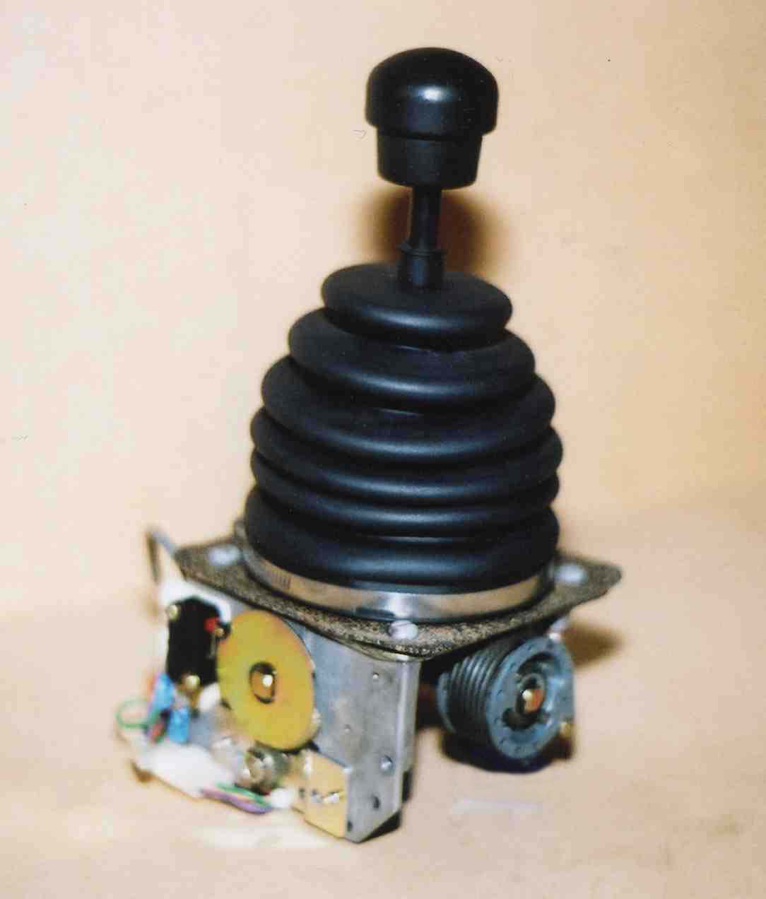
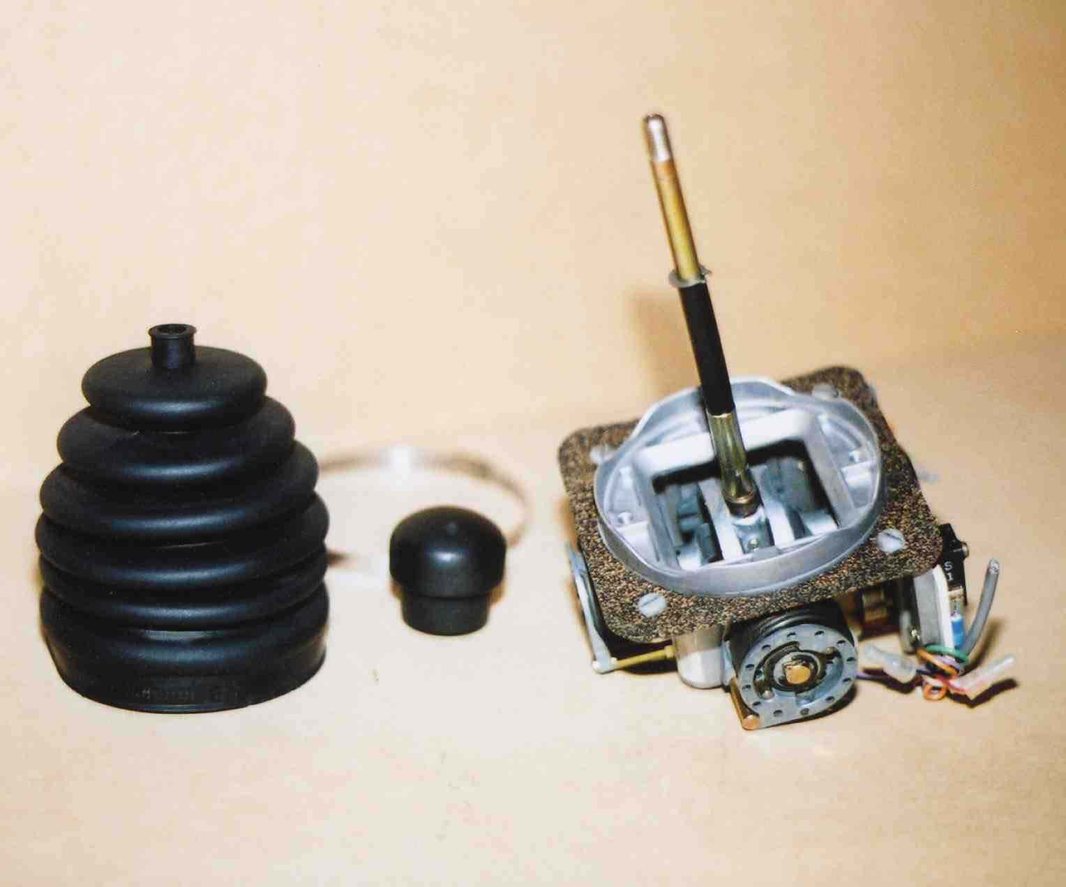
One of these pod hand controllers is also used in the lunar bus, Aires, and Orion for each pilot, in addition to a vertical control grip. Several years ago, when working on the 2001 spacesuit restoration, I came across a photo of one of the vertical control grips on the Aires set. Using a magnifier to inspect the image, I noticed a small identification plate was attached to the base of the control grip, and I could see a part number. At that point I realized the the vertical control grip was a real piece of hardware, and a slightly modified version (with the base cut off) was used for the hand controller on the Discovery spacesuit chest pack. I was able to obtain several original control grips of this type for use on the spacesuit. These vertical control grips were also used in the lunar bus, the Aires, and Orion cockpits. I thought the pod attitude hand controller could also be real hardware, but I have been unsuccessful in identifying it. There is some evidence it may have been something made for the film, but it is very well done and is constructed to match the design of "real" control grips. This true in the use of the unique texturized coating that is characteristic of British control grips. What is obvious is, there are left and right hand versions of them. I figured I could always make them from scratch if I had to, but it would be better if I could find originals, if they indeed exist. More about this later.
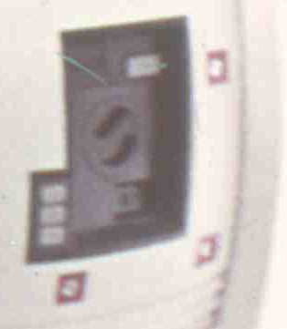
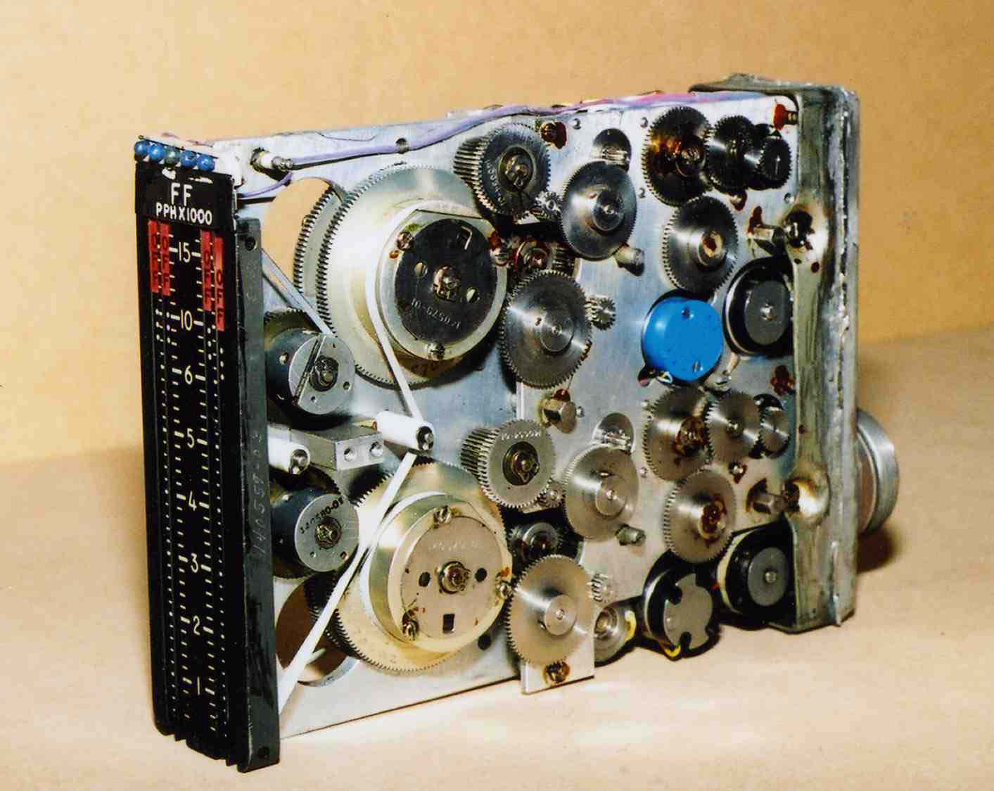
Besides the hand controllers, one of the more complicated parts for the pod interior was the explosive bolt arming unit. This would be a difficult item to reproduce as it is complicated with many parts. It is fairly clearly shown in the film, and again looks as though it is real hardware that was adapted for the film. Well, not too long ago while I was looking at some photos of the pod interior, I had a feeling like I had seen that device before. Some time later, it suddenly hit me as to what was used for the control unit. I then began looking for the correct version, and finally was successful in obtaining one of the units. Ths saved a lot of work and was the turning point for accelerating work on reproducing the pod.
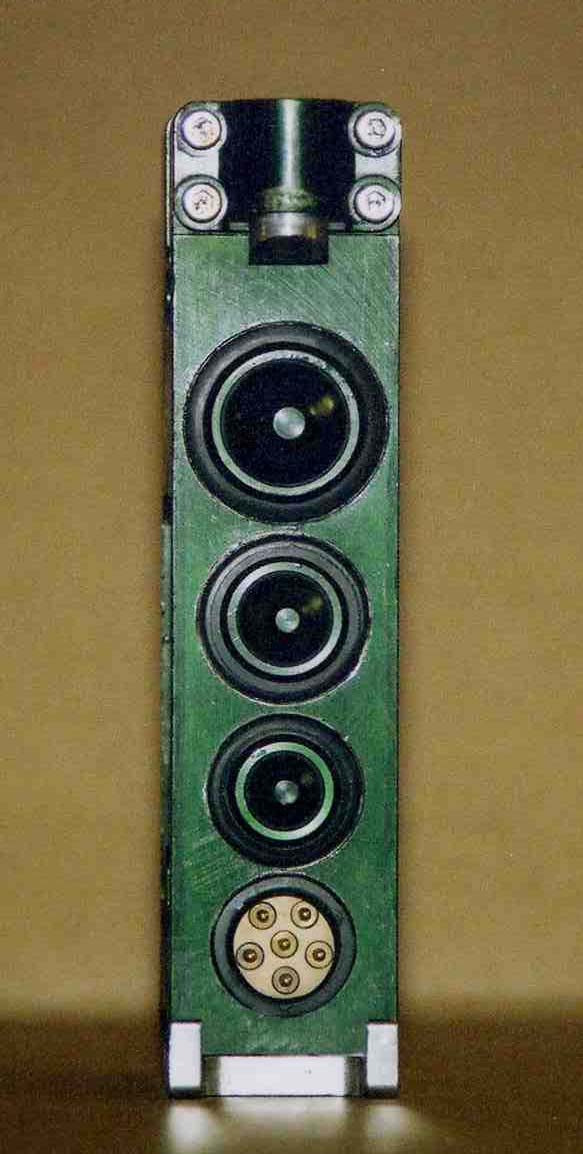
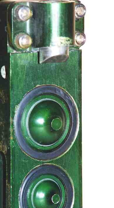
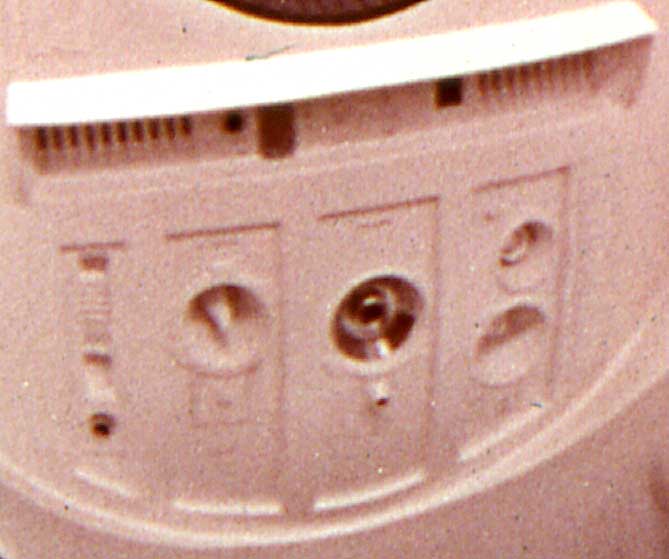
This is the same type of device as was modified for use as the explosive bolts arming control unit. Protective cover is removed. The unit has a protective cover whch comes off, revealing 3 firing switches. While the arming switches that Bowman pushes in the film look like balls, they actually are a slightly different shape with small stubs protruding in the center of the ball. They have the shape of a champaign glass bowl if the stem is broken off, leaving a short stub.
Close-up showing detail of explosive bolt arming switch buttons. Once I saw this I checked the film again, and the stubs are actually visible, once you know what to look for. This is the kind of subtle detail you can only get by having the same equipment as was used to make the original pods. Some metal parts need to be machined and added to the removable cover to complete the unit per the film images.